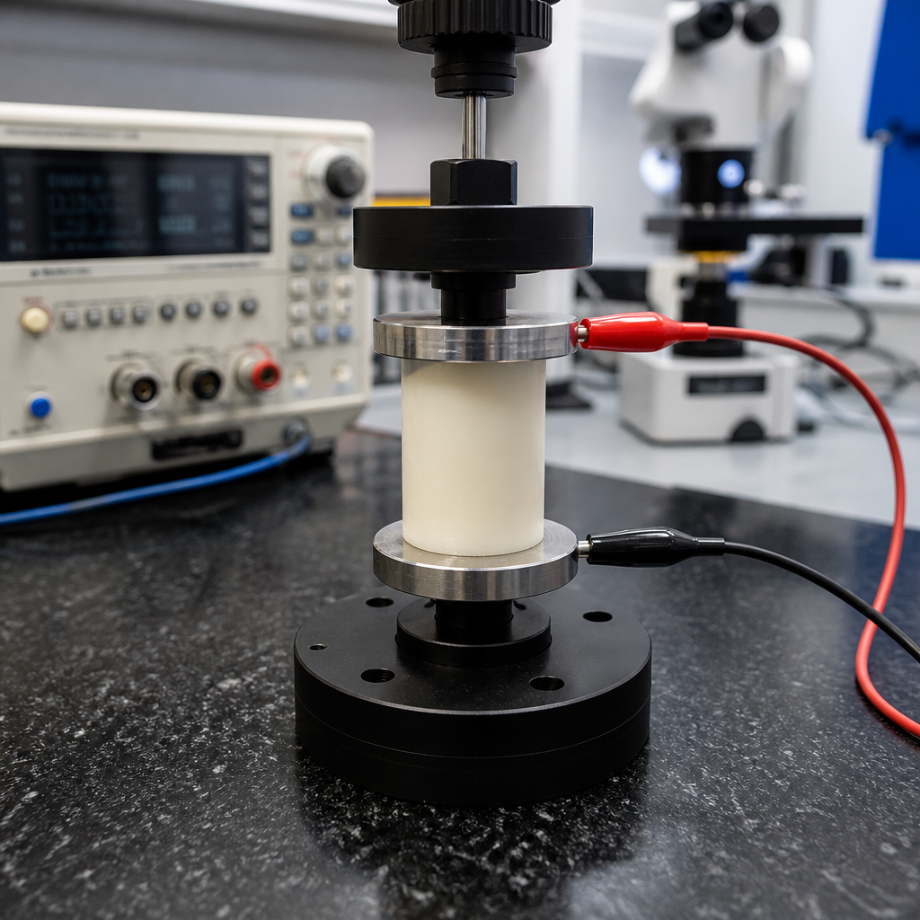
Evaluating the volume resistivity of polymer materials is fundamental to understanding how plastics behave in electrical applications, from wire insulation and connectors to antistatic packaging, medical devices, and high-voltage components. Volume resistivity is the measure of a material’s resistance to current flowing through its bulk, usually expressed in ohm-centimeters or ohm-meters, and it differs from surface resistivity, which describes leakage along the material’s exterior. In practice, these two properties are closely related, but they answer different engineering questions. When I evaluate electrical properties for polymer selection, volume resistivity is often the first screening metric because it quickly tells whether a resin will act as an insulator, a dissipative material, or, when heavily modified, something closer to a conductor.
This topic matters because polymers rarely operate in ideal laboratory conditions. Temperature, humidity, contamination, additives, molding history, crystallinity, and aging can all change electrical performance by orders of magnitude. A nylon that looks highly insulating on a dry data sheet may lose resistivity dramatically after moisture uptake. A carbon-filled polyethylene designed for electrostatic discharge protection may perform well at one filler loading and fail at another because the conductive network is not yet continuous. Engineers responsible for reliability, safety, and compliance need more than a single number; they need a framework for interpreting electrical properties across materials, test methods, and service environments. As the hub for electrical properties within materials and properties, this article connects volume resistivity to dielectric strength, dielectric constant, dissipation factor, arc resistance, insulation resistance, and electrostatic discharge behavior so material decisions are made on complete evidence.
What volume resistivity means and how it fits within electrical properties
Volume resistivity quantifies the intrinsic opposition of a polymer to direct current passing through its thickness. In a standard test, electrodes contact opposite faces of a specimen, a voltage is applied, and the resulting current is measured after a defined electrification time. Resistivity is then calculated from resistance adjusted for sample geometry. High values indicate strong insulating behavior. Typical unfilled fluoropolymers, polyethylene, polypropylene, and polystyrene are extremely resistive, while filled compounds containing carbon black, carbon fiber, stainless fibers, or intrinsically conductive additives can be engineered into dissipative or conductive ranges.
Electrical properties should be evaluated as a system, not a checklist. Volume resistivity addresses bulk DC conduction, but it does not reveal how a material behaves under rapidly alternating fields, high voltage stress, or contaminated surfaces. Dielectric constant affects capacitance and signal propagation. Dissipation factor reflects dielectric losses and heat generation in AC service. Dielectric strength measures breakdown voltage per unit thickness. Comparative tracking index and arc resistance matter where contamination and arcing are possible. Surface resistivity and static decay become critical in electronics packaging and semiconductor environments. A robust materials review places volume resistivity at the center, then uses adjacent properties to confirm the material’s actual fitness for use.
How volume resistivity is tested in the laboratory
The most widely cited method is ASTM D257, Standard Test Methods for DC Resistance or Conductance of Insulating Materials. Many specifications also reference IEC 60093 for solid electrical insulating materials. Both methods require careful specimen preparation, controlled electrode geometry, and environmental conditioning because very small leakage currents are being measured. In my experience, the quality of guarding and fixturing matters as much as the electrometer itself. A poorly cleaned fixture, fingerprints on the specimen, or unstable humidity can distort results enough to make one material appear better or worse than it really is.
Testing usually involves a flat plaque or machined specimen of known dimensions. Guarded electrodes are used to force current through the bulk while minimizing edge leakage. The applied voltage may vary depending on the expected resistivity range, and the sample is conditioned at specified temperature and relative humidity before measurement. Because current in polymers often decays with time due to polarization effects, the report should state electrification time, conditioning history, test temperature, humidity, specimen thickness, and voltage. If any of these are missing, comparisons between suppliers become unreliable. This is one reason broad data sheet values should be treated as orientation, not design limits.
Key variables that change the result
Several variables can shift measured volume resistivity by one or more decades. Moisture is the most common factor. Hygroscopic polymers such as polyamide, polycarbonate to a lesser extent, TPU, and some polyesters can absorb water that increases ionic conduction. Temperature is equally important because charge mobility generally rises as polymers warm. Additives also matter: plasticizers, flame retardants, antistatic agents, pigments, stabilizers, and residual catalyst species can all alter conductivity. Processing history influences crystallinity, void content, orientation, and dispersion of fillers, which in turn affects electrical pathways.
Thickness and test voltage can also change the apparent answer if the material shows non-ohmic behavior or contains defects. Regrind content sometimes shifts performance because contamination and thermal history alter molecular structure. For filled compounds, dispersion quality is decisive. I have seen nominally identical carbon-black ESD grades differ substantially lot to lot because the percolation network was better developed in one production campaign than another. That is why serious qualification plans include repeat testing across lots, molded conditions, and post-conditioning states rather than relying on a single plaque measured once in a dry lab.
Typical resistivity ranges for common polymer families
Although exact values depend on grade and conditions, broad ranges help frame material selection. Commodity polyolefins such as PE and PP are usually excellent insulators. PTFE and other fluoropolymers are among the highest-resistivity materials used in production. ABS, PC, PBT, PET, PSU, and PEEK are also insulating when unfilled, but they vary in humidity sensitivity and dielectric loss. Nylon deserves special caution: dry-as-molded nylon can look highly resistive, yet conditioned nylon may drop sharply, which can be either acceptable or problematic depending on the application.
| Material type | Typical volume resistivity behavior | Common use implication |
|---|---|---|
| Unfilled PE, PP, PTFE | Very high insulating range | Good for insulation, cable jackets, dielectric parts |
| Unfilled ABS, PC, PBT, PEEK | High insulating range | Suitable for housings and structural electrical components |
| Nylon and hygroscopic polymers | High when dry, lower after moisture uptake | Needs conditioned-state validation |
| Antistatic modified polymers | Intermediate dissipative range | Reduces static buildup on packaging and trays |
| Carbon-filled ESD or conductive compounds | Low resistivity once filler network percolates | Used for grounding, EMI control, and static dissipation |
These ranges are directional, not universal acceptance criteria. The same base resin can move from insulating to dissipative with additive packages, humidity exposure, or contamination. When evaluating supplier data, check whether the number is a minimum, typical, or conditioned value and whether the test references ASTM D257 or IEC 60093. If the intended environment includes washdown, sterilization, outdoor weathering, or elevated temperature, ask for post-exposure data. That request alone often reveals whether a grade has been characterized deeply or only marketed broadly.
Interpreting results for design, compliance, and failure analysis
A high volume resistivity value is not automatically better. The right target depends on function. For high-voltage insulation, very high resistivity usually supports low leakage current and stable insulating performance, but only if dielectric strength, tracking resistance, and long-term aging also meet requirements. For electronics handling, a polymer that is too insulating can accumulate charge and create electrostatic discharge risk. In those cases, a dissipative material may be preferable even though its resistivity is much lower than a classic insulator. The engineering question is always application-specific: prevent current flow, manage charge, or create a controlled conductive path.
Resistivity also helps during failure analysis. If a connector housing starts leaking current in humid service, comparing as-received and humidity-conditioned volume resistivity can identify whether water uptake is driving the issue. If a molded battery component fails dielectric testing sporadically, mapping resistivity across sections may reveal contamination, voids, or inconsistent filler distribution. For overmolded assemblies, unexpected current paths may come from flash, carbonized residues, or ionic contamination rather than the nominal resin. In quality investigations, resistivity data becomes more powerful when paired with FTIR for contamination, DSC for crystallinity, TGA for filler content, and microscopy for structural defects.
Relationship to dielectric strength, permittivity, loss, and insulation resistance
Electrical properties are often confused because they all describe “insulation,” yet they are not interchangeable. Volume resistivity concerns steady-state DC conduction through the bulk. Dielectric strength is the electric field at breakdown and says how much voltage the material can survive briefly without catastrophic failure. Relative permittivity, also called dielectric constant, indicates how strongly the material polarizes in an electric field, which affects capacitance. Dissipation factor or tan delta measures dielectric losses under AC conditions. Insulation resistance is a component-level metric influenced by geometry, interfaces, and contamination, not just the material itself.
Consider two materials for a sensor housing. Both may show high volume resistivity, but one could have a higher dielectric constant that changes signal behavior, while the other could have a lower dielectric strength that limits wall-thickness design. In motor insulation systems, low dielectric loss may matter as much as high resistivity because heat from AC fields accelerates aging. In high-frequency electronics, stable permittivity and low loss are often more relevant than extraordinary DC resistance. This is why electrical material selection should never stop at one property table. Good practice is to review the complete electrical profile alongside mechanical, thermal, chemical, and processing data.
Choosing the right polymer for insulating, dissipative, and conductive applications
For insulating applications, unfilled fluoropolymers, polyolefins, PPS, PEEK, and many engineering thermoplastics are strong candidates, but selection still depends on temperature, moisture, flammability, and dimensional stability. Cable insulation may favor XLPE or fluoropolymers for dielectric reliability and heat resistance. A medical handle may prioritize biocompatibility, sterilization resistance, and cleanability. For dissipative applications, permanent antistatic additives, inherently dissipative polymers, or low-level conductive filler systems can control charge without making parts fully conductive. Temporary topical antistats are cheaper but can wash off, bloom, or lose effectiveness over time.
Conductive polymers typically rely on fillers such as carbon black, carbon nanotubes, carbon fiber, metal fiber, or graphite. Their performance depends on reaching a percolation threshold where conductive pathways connect through the matrix. Above that threshold, resistivity can drop sharply with small formulation changes. The tradeoff is that conductive fillers can reduce impact strength, alter shrinkage, increase anisotropy, and affect surface appearance. They may also complicate molding due to viscosity changes. When I specify an ESD-safe material, I ask for both electrical targets and processing windows because the best lab formulation is not useful if production cannot hold the filler network consistently across thin ribs, weld lines, and regrind limits.
Best practices for specifying and validating electrical properties
Start with the service environment and failure mode, not the data sheet. Define whether the part must insulate, dissipate, or conduct; then set measurable acceptance criteria for dry and conditioned states. Reference the test method, specimen geometry, conditioning, temperature, humidity, and electrification time directly in the material specification. If the component will see solder reflow, sterilization, outdoor UV, coolant exposure, or elevated continuous use temperature, require post-exposure retesting. For regulated sectors, link polymer properties to the finished-part verification plan so material compliance and product compliance are connected rather than assumed.
Use supplier data for shortlisting, but validate with molded parts from representative tools and processing conditions. Include multiple lots, because electrical properties can vary with additive dispersion and moisture history. Review adjacent metrics such as dielectric strength, CTI, RTI where applicable, UL recognition status, and flammability classification. If the part manages static around electronics, test surface resistivity and static decay in addition to volume resistivity. The core benefit of this disciplined approach is simple: it reduces surprises. Better specifications produce better material choices, faster approvals, and more reliable electrical performance in the field. Audit your current polymer selections against actual service conditions, then close the gaps with targeted testing.
Frequently Asked Questions
What is volume resistivity, and why is it important when evaluating polymer materials?
Volume resistivity describes how strongly a polymer resists the flow of electrical current through its bulk, rather than along its outer surface. It is commonly reported in ohm-centimeters (Ω·cm) or ohm-meters (Ω·m), and it serves as a core property when determining whether a plastic will function as an insulator, a static-dissipative material, or a more conductive compound in a finished product. For engineers and materials specialists, this value is essential because it helps predict how a polymer will behave in real electrical environments such as cable insulation, connector housings, sensor components, packaging for sensitive electronics, and medical or high-voltage devices.
The importance of volume resistivity comes from the fact that many polymer applications depend on controlling current flow through the material itself. A high volume resistivity generally indicates strong insulating performance, which is critical in preventing short circuits, current leakage, dielectric breakdown, or unintended energy transfer. A lower volume resistivity may be desirable in antistatic or electrostatic discharge-sensitive applications, where the goal is to dissipate charge in a controlled way rather than trap it. Because plastics can vary dramatically depending on resin type, fillers, additives, moisture uptake, and processing history, volume resistivity gives a measurable way to compare materials and confirm whether a formulation is suitable for its intended electrical role.
How is volume resistivity different from surface resistivity in polymers?
Volume resistivity and surface resistivity are closely related electrical properties, but they describe different current paths and are used for different kinds of performance evaluation. Volume resistivity measures resistance to current passing through the interior of the polymer, essentially through its thickness and bulk structure. Surface resistivity, by contrast, measures resistance to current moving across the outer surface of the material. This distinction matters because a polymer may perform very differently internally than it does externally, especially when exposed to humidity, contamination, oils, dust, or processing residues.
In practical terms, volume resistivity is often more relevant when the polymer is serving as a true electrical barrier or dielectric, such as in insulation systems, molded electrical parts, and high-voltage components. Surface resistivity becomes especially important in applications where static charge accumulates or where leakage may occur along the exposed exterior, such as trays, packaging, work surfaces, and handling equipment for electronics. For example, a material could have excellent bulk insulation but still show lower surface resistance if moisture films or conductive contaminants are present. That is why both measurements are often considered together when selecting a polymer for electrical service. Understanding the difference helps prevent design errors and ensures that testing reflects actual field conditions rather than only one aspect of electrical behavior.
What factors can affect the measured volume resistivity of a polymer material?
Volume resistivity in polymers is influenced by a wide range of material, environmental, and testing variables, which is why consistent methods are so important. At the material level, polymer chemistry is one of the biggest drivers. Different base resins naturally exhibit different insulating behavior, and the presence of additives such as carbon black, flame retardants, plasticizers, stabilizers, conductive fillers, antistatic agents, glass fibers, or mineral reinforcements can shift resistivity significantly. Even small formulation changes may alter charge transport pathways through the bulk of the material.
Moisture content is another major factor. Many polymers absorb some degree of water, and that absorbed moisture can lower resistivity by increasing ionic conduction. Temperature also plays a critical role, since higher temperatures generally increase molecular mobility and may reduce resistivity. Sample thickness, molding conditions, residual stresses, crystallinity, orientation, and post-processing steps such as annealing or drying can all influence the result as well. In addition, contamination from handling, incomplete conditioning, or inconsistent electrode contact may skew measurements. Because of these variables, volume resistivity values should always be interpreted in the context of clearly defined test conditions. Comparing numbers from different sources without checking the temperature, humidity, conditioning time, and test standard can lead to misleading conclusions about how a polymer will actually perform.
How is volume resistivity typically tested for polymer materials?
Volume resistivity is typically evaluated by preparing a polymer specimen of known dimensions, placing electrodes on or against the sample, applying a DC voltage, and measuring the resulting current through the bulk of the material. From that measured resistance and the sample geometry, the volume resistivity can be calculated. Standardized methods are often used to improve repeatability and comparability, with laboratories commonly following recognized test procedures that define specimen preparation, conditioning, electrode arrangement, applied voltage, electrification time, and calculation methods.
Good testing practice is especially important because polymers are sensitive to environmental conditions and may require time to stabilize after voltage is applied. In many cases, the specimen is conditioned at a specified temperature and relative humidity before testing. The choice of voltage and the duration of electrification can affect the reading, particularly for highly resistive materials where absorption currents and polarization effects may be present. Electrode design also matters, since the setup must isolate bulk conduction as much as possible and minimize errors from surface leakage. The resulting data are most meaningful when accompanied by full test details, including specimen thickness, conditioning environment, temperature, humidity, and standard used. Without that context, a volume resistivity value is incomplete and much harder to apply confidently in design, material selection, or quality control.
How should engineers and buyers use volume resistivity data when selecting a polymer for electrical applications?
Volume resistivity data should be used as a decision-making tool, not as a standalone pass-fail number. For engineers, the first step is to match the resistivity range of the polymer to the needs of the application. If the component must act as a strong insulator, a high volume resistivity is generally preferred to reduce bulk current flow and improve electrical isolation. If the product is intended to control electrostatic charge, such as antistatic packaging or static-dissipative parts, then a lower and more controlled resistivity range may be more appropriate. The key is understanding the electrical function the polymer must serve under actual service conditions.
Buyers and specifiers should also look beyond a single catalog value. They should confirm whether the reported data come from a recognized test standard, whether the material was tested in dry or humid conditions, and whether the formulation is natural, filled, reinforced, or modified with conductive or antistatic additives. It is also wise to review related properties such as surface resistivity, dielectric strength, comparative tracking behavior, moisture absorption, and long-term thermal performance. In regulated or high-reliability sectors like medical, automotive, aerospace, or power distribution, qualification testing under end-use conditions is often necessary before final approval. In other words, volume resistivity is one of the most informative electrical properties for polymer selection, but it delivers the most value when considered alongside formulation details, environmental exposure, processing history, and the real demands of the final application.