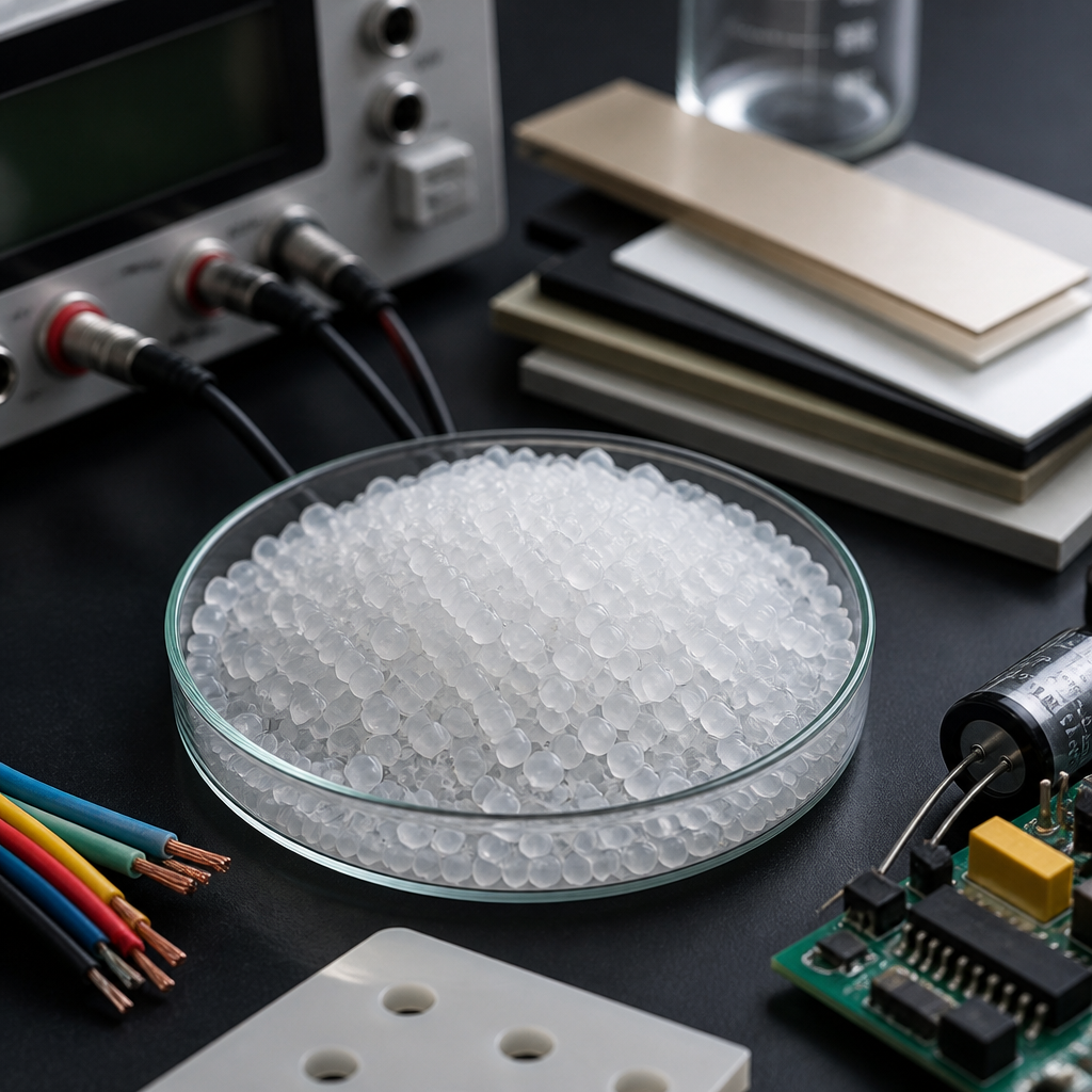
Understanding the dielectric constant of polymers starts with a simple idea: every polymer responds to an electric field, and that response influences insulation performance, signal transmission, energy storage, and product reliability. In materials engineering, the dielectric constant, also called relative permittivity, measures how much electrical energy a material can store compared with vacuum. For polymers, this value is not fixed in a practical sense. It shifts with frequency, temperature, humidity, morphology, additives, and processing history. I have seen the same nominal resin grade produce meaningfully different electrical behavior after changes in drying, filler loading, or annealing, which is why engineers treat dielectric data as application specific rather than merely a catalog number.
For readers working across the broader materials and properties landscape, electrical properties form a core decision layer alongside mechanical, thermal, chemical, and optical performance. This hub article focuses on the dielectric constant of polymers because it connects directly to nearly every electrical design question. If you are choosing a cable insulation, a printed circuit substrate, a sensor housing, a capacitor film, or a radome, the dielectric constant affects capacitance, impedance, electric field distribution, insertion loss, and miniaturization limits. It also links to related properties that deserve separate deep dives, including dielectric strength, dissipation factor, volume resistivity, surface resistivity, tracking resistance, arc resistance, and electrostatic behavior.
In plain terms, a higher dielectric constant means a polymer polarizes more strongly when voltage is applied. That can be useful in capacitors and embedded passives, but it can be a drawback in high speed electronics where low permittivity helps preserve signal integrity. The key terms matter. Polarization is the alignment or displacement of charges within the material. Frequency matters because different polarization mechanisms respond at different speeds. Dielectric loss matters because a polymer can store electric energy and still waste part of it as heat. Standards matter too. Most reliable dielectric data come from controlled tests such as ASTM D150 or IEC methods, with specified frequency and temperature. Without those conditions, a dielectric constant value is only half information.
This page serves as a hub for electrical properties within polymer selection and design. It explains what dielectric constant means, what controls it, how common polymers compare, where the tradeoffs appear, and how to interpret data sheets without being misled. The goal is practical understanding: enough depth to choose materials more confidently, ask better questions of suppliers, and connect dielectric constant to real product performance rather than treating it as an isolated number.
What dielectric constant means in polymers
The dielectric constant of a polymer is the ratio of its permittivity to the permittivity of free space. A value of 2.2 means the material stores about 2.2 times as much electric energy as vacuum under the same field conditions. In polymer systems, the dominant contributors are electronic polarization, atomic polarization, dipolar orientation, and, in some cases, interfacial polarization. Nonpolar polymers such as PTFE and polyethylene usually have lower dielectric constants because they lack strong permanent dipoles. Polar polymers such as nylon, PVC, and PVDF tend to have higher values because their molecular groups reorient more strongly in an electric field.
That molecular explanation is not academic detail; it predicts behavior. Fluoropolymers often combine low dielectric constant with excellent chemical resistance, which is why PTFE is common in high frequency cable and microwave assemblies. By contrast, PVDF has a much higher dielectric constant and is used where stronger polarization is desirable, including sensors and specialty films. Semi-crystalline structure also matters. Crystalline regions often respond differently from amorphous regions, and the degree of crystallinity can shift the measured permittivity. Processing conditions that alter orientation, void content, or residual moisture can therefore move electrical properties enough to affect a design margin.
The dielectric constant is always tied to test conditions. A polymer may show one value at 1 kHz and another at 1 MHz or 10 GHz. This happens because slower polarization mechanisms can follow low frequency fields but not rapid high frequency reversals. Temperature has a similar effect, especially near glass transition, where molecular mobility changes sharply. Moisture uptake can raise permittivity because water has a very high dielectric constant, around 80 at room temperature. In hygroscopic polymers such as polyamide, even modest moisture absorption can change measured electrical properties far more than many engineers expect from a dry as molded data sheet.
Why dielectric constant matters in real applications
Dielectric constant influences electrical design in direct, measurable ways. In a capacitor, capacitance rises with permittivity, so a higher dielectric constant allows more energy storage in the same geometry. In a transmission line or printed circuit structure, the effective dielectric constant affects propagation delay and characteristic impedance. In antenna covers and radomes, lower and more stable permittivity reduces signal distortion. In high voltage insulation, dielectric constant influences field concentration, especially across interfaces between dissimilar materials. When I review failures in connectors or encapsulated electronics, mismatched permittivity at boundaries is often part of the stress story, not just dielectric strength.
For consumer electronics, low dielectric constant polymers support thinner, faster signal pathways and reduced parasitic capacitance. Liquid crystal polymer, PTFE composites, and certain polyolefins are used in advanced interconnects because they help maintain signal integrity at high frequencies. In wire and cable, polyethylene and crosslinked polyethylene remain central because they pair favorable dielectric behavior with processability and cost effectiveness. In film capacitors, polypropylene is widely used because it combines low dielectric loss, good breakdown behavior, and stable performance over a useful temperature range. These choices are not interchangeable; the right polymer depends on whether the design priority is speed, energy storage, insulation, flexibility, or environmental resistance.
| Polymer | Typical dielectric constant | Common use | Key reason |
|---|---|---|---|
| PTFE | About 2.0 to 2.2 | RF cable, microwave laminates | Very low permittivity and low loss |
| Polyethylene | About 2.2 to 2.4 | Wire and cable insulation | Low cost with good electrical insulation |
| Polypropylene | About 2.2 to 2.3 | Capacitor films | Low loss and strong dielectric performance |
| Epoxy systems | About 3.0 to 4.5 | PCB matrices, encapsulation | Balanced structural and electrical properties |
| Nylon | About 3.2 to 4.0 dry | Connectors, housings | Good engineering performance but moisture sensitive |
| PVDF | About 8 to 13 | Sensors, specialty films | High polarity and strong electroactive response |
What controls dielectric constant: chemistry, structure, and environment
The first control is polymer chemistry. Nonpolar backbones with symmetrical structures usually yield lower dielectric constants. Adding polar functional groups such as carbonyl, amide, nitrile, or chloride generally increases permittivity. Fluorination is a useful nuance: some fluoropolymers stay low because their molecular architecture limits net dipole response even though carbon fluorine bonds are individually polar. The second control is morphology. Amorphous and crystalline phases respond differently, and interfaces between phases can create interfacial polarization. Filler selection matters as well. Glass fiber, ceramic particles, carbon additives, flame retardants, and plasticizers can all shift dielectric behavior, sometimes intentionally and sometimes as a side effect.
The third control is environment. Frequency dependence is fundamental. At low frequencies, dipoles have more time to orient, often raising dielectric constant. At very high frequencies, only the fastest mechanisms contribute. Temperature dependence can be mild or pronounced depending on polymer mobility and transitions. Near the glass transition temperature, dielectric behavior may change sharply because chain segments gain freedom to move. Humidity is often the most underestimated variable. Materials such as polyamide, PBT, PET, and polycarbonate can show electrical shifts after conditioning. In production, I have seen a connector pass bench testing when dry, then drift electrically after humidity exposure because absorbed moisture changed both permittivity and loss.
Processing also leaves fingerprints. Void formation lowers effective permittivity and can create localized field intensification. Orientation from extrusion or stretching can make dielectric behavior anisotropic, meaning it differs by direction. In foamed polymers, the inclusion of air reduces the effective dielectric constant, which is useful in low permittivity cable insulation and lightweight substrates. Cure state matters for thermosets. Epoxies with different crosslink density, resin hardener ratios, or filler packages can vary enough that one formulation works at GHz frequencies while another is better suited for potting low frequency electronics. Because of these influences, good electrical design starts with the exact grade, process, and service condition, not just the base polymer family.
How engineers measure and interpret dielectric data
Reliable dielectric constant data come from standardized methods and careful interpretation. ASTM D150 is one of the most commonly cited standards for AC loss characteristics and permittivity of solid electrical insulation. IEC test methods are also widely used internationally. The test setup may involve parallel plate electrodes, guarded fixtures, resonant methods, or network analyzer techniques at higher frequencies. The method matters because fringe effects, specimen thickness, electrode contact, and calibration all affect results. If a data sheet lists dielectric constant without frequency, temperature, or conditioning state, treat it as incomplete. In practice, engineers need a curve or at least several points across the intended operating range.
Interpreting dielectric data also requires separating dielectric constant from related properties. A polymer can have a suitable dielectric constant but still fail because its dissipation factor is too high, causing heating under alternating fields. It can also have good permittivity and poor dielectric strength, making it vulnerable to breakdown at high voltage. Volume resistivity and surface resistivity address leakage pathways, while comparative tracking index relates to resistance against conductive path formation on the surface. For this reason, dielectric constant is a hub property within electrical properties, not a stand alone decision metric. Good material selection considers the full electrical profile and the geometry of the finished part.
At high frequencies, engineers often use the term dielectric constant alongside dielectric loss tangent or dissipation factor because signal integrity depends on both. A low Dk material with high loss may still be a poor choice for RF applications. That is why PTFE based laminates, low loss hydrocarbon ceramic systems, and certain liquid crystal polymer materials are valued in antennas and microwave circuits. In lower frequency power applications, stability over temperature and moisture may matter more than absolute minimum permittivity. The correct question is never simply, “What is the dielectric constant of this polymer?” The useful question is, “What is its dielectric behavior under my electrical, thermal, and environmental conditions?”
How to choose the right polymer for electrical properties
Start with the application function. If the polymer is primarily an insulator around conductors, prioritize stable dielectric constant, high dielectric strength, low moisture sensitivity, and process consistency. If it is part of a signal path, low permittivity and low loss become more important. If the application is energy storage, a higher dielectric constant may be beneficial, but only if loss and breakdown behavior remain acceptable. For connectors and housings, dimensional stability, flame performance, and mechanical durability may weigh as heavily as dielectric properties. This is why electrical material selection rarely ends with one property chart; it is a cross functional decision linking design, processing, reliability, and compliance.
A practical screening method is to compare four things at once: dielectric constant at the relevant frequency, dissipation factor, moisture absorption, and operating temperature range. For example, polypropylene and PTFE both offer low permittivity, but PTFE handles harsher chemical and temperature environments at a much higher material and processing cost. Nylon offers strong mechanical performance for connectors, yet its moisture sensitivity can complicate precision electrical behavior. Epoxy systems are indispensable in many electronic assemblies because they bond well and carry structural load, but their dielectric properties depend strongly on formulation. In other words, the best polymer for electrical properties is the one whose complete performance envelope matches the use case.
As a hub within materials and properties, this topic naturally points to related articles on dielectric strength, dielectric loss, insulation resistance, surface resistivity, electrostatic discharge behavior, and high frequency polymer selection. Understanding the dielectric constant of polymers gives you the anchor concept for all of them. It tells you how the material interacts with an electric field, which then shapes capacitance, impedance, field distribution, and often long term reliability. Use supplier data carefully, confirm with application specific testing, and ask for frequency and conditioning details whenever values seem too generic. When you do that, dielectric constant stops being a mysterious catalog figure and becomes a practical tool for smarter materials selection.
Frequently Asked Questions
What is the dielectric constant of a polymer, and why does it matter?
The dielectric constant of a polymer, also called relative permittivity, describes how effectively that material can store electrical energy when it is placed in an electric field. It is expressed relative to vacuum, which has a value of 1. In practical terms, a higher dielectric constant means the polymer can polarize more strongly in response to an applied field, while a lower dielectric constant means it stores less electrical energy and often behaves as a better low-loss insulator for high-speed electronic applications.
This property matters because it directly affects how polymer materials perform in real products. In wire and cable insulation, the dielectric constant influences capacitance, signal delay, and energy dissipation. In printed circuit boards, connectors, and microelectronic packaging, it plays a major role in signal integrity and high-frequency performance. In capacitors and energy storage systems, it helps determine how much charge can be stored in a given geometry. It also affects electric field distribution, which can influence breakdown behavior, reliability, and long-term aging.
For engineers, the dielectric constant is not just a number pulled from a datasheet. It is a design parameter that helps guide material selection based on the end-use environment. A polymer chosen for high-voltage insulation may need predictable permittivity and low dielectric loss over a wide temperature range, while a polymer used in communication devices may need especially low dielectric constant values to reduce delay and crosstalk. Understanding the dielectric constant helps connect molecular structure to electrical performance, making it one of the most important electrical properties in polymer engineering.
Why is the dielectric constant of polymers not truly fixed?
The dielectric constant of polymers is often presented as a single value, but in reality it changes with testing conditions and material state. That is because polarization in polymers is not controlled by one mechanism alone. Several processes contribute to the overall response, including electronic polarization, atomic or ionic displacement, dipolar orientation, and in some systems interfacial polarization. Each of these mechanisms responds differently depending on how quickly the electric field changes and what thermal energy is available within the material.
Frequency is one of the most important reasons the dielectric constant shifts. At low frequencies, dipolar groups in the polymer chain may have enough time to align with the changing field, which raises the measured permittivity. As frequency increases, some of these slower polarization mechanisms can no longer keep up, so the dielectric constant often decreases. This is why a polymer can show one value in power-frequency testing and a different value in radio-frequency or microwave applications.
Temperature also changes dielectric behavior. As the polymer warms, chain mobility usually increases, making dipole motion easier in some temperature ranges and potentially increasing the dielectric constant. Near relaxation transitions, especially around the glass transition region, dielectric behavior can change significantly. Moisture absorption can further alter results because water has a high dielectric constant and can introduce additional polarization and loss. Crystallinity, filler content, orientation, additives, and processing history can all shift measured values as well. Because of these variables, the dielectric constant of a polymer should always be interpreted together with the frequency, temperature, humidity, and test method used to obtain it.
How do frequency and temperature affect the dielectric constant of polymers?
Frequency and temperature are two of the strongest influences on polymer permittivity because they control how molecular dipoles and charge distributions respond to an applied electric field. When a low-frequency field is applied, polar segments within the polymer often have enough time to reorient with each cycle. That additional molecular alignment contributes to a higher dielectric constant. As the field frequency rises, those dipoles begin to lag behind. Once the field changes too quickly for a particular polarization mechanism to follow, its contribution drops out, and the measured dielectric constant falls.
This behavior is closely connected to dielectric relaxation. Different motions within a polymer occur on different time scales, so the material does not respond uniformly across the full frequency spectrum. A polymer that performs well in low-frequency insulation may behave quite differently at microwave frequencies. This is especially important in modern electronics, where material selection depends not only on permittivity but also on stability across wide operating ranges. A datasheet value measured at 1 kHz may not represent the same material accurately at GHz frequencies.
Temperature adds another layer of complexity. As temperature increases, polymer chains and dipolar side groups often gain mobility, which can increase polarization and alter relaxation behavior. In some cases the dielectric constant rises because dipoles are more able to orient. In other cases, structural changes, thermal expansion, or changes in phase morphology can shift the response in more complicated ways. Around glass transition temperatures, the change can be especially pronounced because the polymer moves from a more rigid to a more mobile state. This is why reliable dielectric characterization requires mapping properties over the frequency and temperature range relevant to the intended application rather than relying on a single room-temperature measurement.
What material factors influence the dielectric constant of a polymer?
The dielectric constant of a polymer is strongly influenced by its molecular structure. Polymers with nonpolar backbones and few permanent dipoles, such as many fluoropolymers and polyolefins, generally have lower dielectric constants because they offer limited dipolar polarization. By contrast, polymers containing polar functional groups, such as carbonyl, hydroxyl, nitrile, or ether groups, often show higher permittivity because those groups can align with the electric field and increase stored energy. In general, the more polarizable the molecular structure, the greater the dielectric response tends to be.
Morphology also matters. Amorphous and crystalline regions contribute differently to electrical behavior because molecular mobility and packing density are not the same in each phase. Crystallinity can reduce dipole mobility in some systems, while interfacial regions between crystalline and amorphous domains may introduce additional effects. Orientation from processing, such as stretching or flow-induced alignment, can create anisotropy, meaning the dielectric constant may differ depending on the direction of measurement. Molecular weight and crosslink density can also influence chain motion and therefore dielectric response.
In real-world formulations, additives often have a major impact. Fillers, plasticizers, flame retardants, stabilizers, pigments, and reinforcing fibers can all change permittivity. High-permittivity ceramic fillers are commonly added when designers want to increase capacitance or tailor field distribution, while porous structures or low-polarity additives may be used to lower the dielectric constant for lightweight or high-speed electronic materials. Moisture uptake is another critical factor, especially for hygroscopic polymers, because absorbed water can raise both dielectric constant and dielectric loss. For that reason, engineers evaluate not only the base polymer chemistry but the full formulation, processing history, and service environment before drawing conclusions about electrical performance.
How is the dielectric constant of polymers measured and used in engineering applications?
The dielectric constant of polymers is measured using electrical test methods that compare a material’s response to an applied electric field under controlled conditions. Common approaches include capacitance-based measurements using parallel-plate electrodes, impedance analysis, LCR meters, dielectric spectroscopy, resonant cavity methods, and network analysis at higher frequencies. The method selected depends on the application range, sample geometry, and frequency of interest. For example, low-frequency measurements may be performed with precision capacitance fixtures, while microwave and millimeter-wave applications require techniques suited to very fast electromagnetic behavior.
Accurate measurement requires careful control of variables. Sample thickness, electrode contact, surface condition, void content, moisture level, temperature, and frequency all influence the result. In some cases, the dielectric constant is reported together with dielectric loss or dissipation factor, since low loss can be just as important as the permittivity value itself. Standards-based testing is especially useful because it allows data to be compared across materials and suppliers. Engineers should always verify whether a reported dielectric constant is a single-point value or part of a broader frequency-temperature characterization.
In engineering applications, the measured dielectric constant helps determine how a polymer will behave as an insulating, structural, or functional material. In cables and insulators, it affects capacitance and electric stress distribution. In antennas, radomes, and RF components, it helps control signal propagation and impedance behavior. In capacitors and embedded electronics, it influences energy storage and device dimensions. In packaging and microelectronics, it plays a key role in timing, crosstalk, and heat-related reliability issues. Because polymer properties can shift with use conditions, engineers rely on dielectric data not only for initial material selection but also for long-term performance prediction, quality control, and failure prevention.