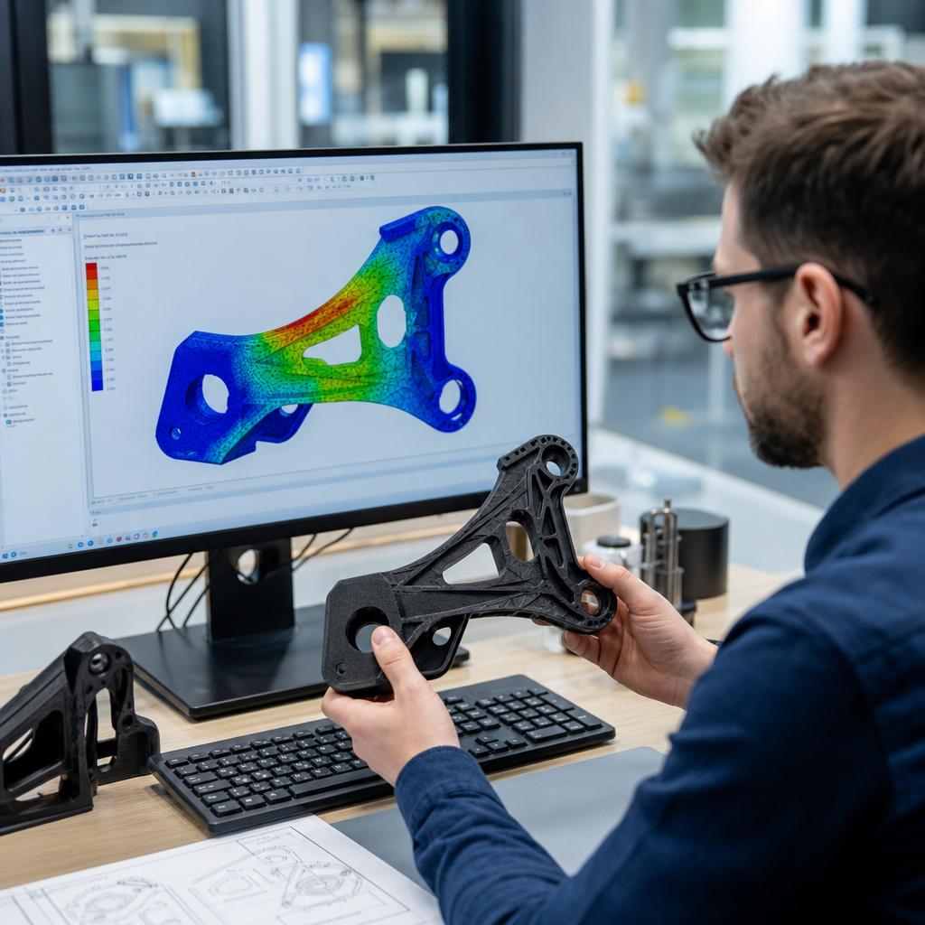
Finite element analysis in polymer engineering turns complex material behavior into solvable numerical models, helping engineers predict how plastic and elastomer parts will deform, heat up, fail, or survive before a tool is cut or a product is launched. In practical terms, finite element analysis, usually shortened to FEA, divides a geometry into many small elements, assigns material laws to those elements, applies loads and constraints, and calculates the response. In polymer engineering, that response is rarely simple, because polymers are viscoelastic, temperature sensitive, anisotropic after processing, and often nonlinear even at moderate strains. I have used FEA on snap-fits, medical housings, under-hood clips, overmolded seals, and fiber-filled nylon brackets, and the lesson is consistent: polymer simulation works best when the analyst understands both the software and the material science behind it.
This matters because polymers are replacing metals in demanding applications where tolerance, durability, weight, and cost are tightly linked. A bracket that passes a room-temperature static check may creep out of position at 80 degrees Celsius. A cosmetic housing may survive assembly once but crack after repeated service access. A molded part may warp because the flow direction created local stiffness differences that a simple isotropic model misses. FEA helps answer those questions early, but only if the right software, inputs, and interpretation methods are used. As a hub for software and tools in educational resources, this guide explains what polymer engineers should expect from FEA, how major platforms fit different needs, which workflows give dependable results, and where simulation should be supported by testing rather than treated as an oracle.
What FEA software does in polymer engineering
FEA software for polymers is used to evaluate structural response, thermal behavior, creep, stress relaxation, impact performance, vibration, and coupled effects such as thermomechanical loading. The core idea is the same across platforms like Ansys Mechanical, Abaqus, COMSOL Multiphysics, Altair OptiStruct, Autodesk Fusion Simulation, and SolidWorks Simulation, but the strength of each tool depends on the problem. For example, Abaqus is widely chosen for advanced nonlinear contact, hyperelasticity, and user-defined material behavior. Ansys Mechanical is strong for broad enterprise workflows, thermal-structural coupling, and integration with CAD and electronics environments. COMSOL is especially useful when polymer behavior interacts with electric fields, diffusion, or custom multiphysics equations. Moldflow and Moldex3D are not classical structural FEA solvers first, but they are essential polymer tools because molding history, fiber orientation, and residual stress often determine the structural answer.
In day-to-day engineering, the first question is not which solver is most famous, but which physics matter. If a polypropylene living hinge cycles thousands of times, fatigue and large strain behavior matter more than a linear stress plot. If a polycarbonate lens holder sees LED heat and screw clamp loads, thermal expansion and contact pressure dominate. If a thermoplastic elastomer seal must compress and recover over time, hyperelastic calibration and compression set are central. Good FEA software supports these cases through material models, element formulations, contact algorithms, and post-processing tools that let engineers inspect strain energy density, principal strain, creep strain, weld-line effects, and safety margins in terms that match failure modes observed in real parts.
Choosing the right software and tools
No single package is best for every polymer engineering task. Selection should be based on material model depth, meshing quality, solver robustness, workflow integration, result traceability, and available expertise. In my experience, companies often overspend on advanced solvers while underinvesting in material data and analyst training, which limits accuracy more than software brand ever does. A structured selection process prevents that mistake.
| Tool | Best use in polymer engineering | Key strength | Main limitation |
|---|---|---|---|
| Abaqus | Nonlinear structural analysis, hyperelastic parts, large deformation, advanced contact | Excellent material model library and solver stability | Steeper learning curve and higher setup effort |
| Ansys Mechanical | General structural and thermal analysis of plastic components | Strong enterprise integration and broad workflow support | Advanced polymer calibration can require additional expertise |
| COMSOL Multiphysics | Coupled thermal, chemical, electrical, and structural polymer problems | Flexible multiphysics modeling | Less common for high-volume structural production workflows |
| Moldflow or Moldex3D | Injection molding simulation, warpage, fiber orientation, residual stress | Captures process-induced properties | Not a substitute for full structural FEA |
| SolidWorks Simulation or Fusion | Early design screening and simple plastic part checks | Fast adoption inside CAD | Limited fidelity for nonlinear polymer behavior |
For educational resources and hub planning, think of these tools as a stack rather than alternatives. CAD-embedded simulation can screen concepts quickly. Mold simulation predicts process effects. A dedicated nonlinear solver validates critical load cases. Material databases, test systems, and scripting tools complete the workflow. Common supporting tools include Granta MI or CAMPUS for material data management, MATLAB or Python for curve fitting, digital image correlation for test validation, and meshing utilities such as HyperMesh for complex models. When teams connect these tools well, FEA becomes a decision system rather than a one-off report.
Building accurate polymer material models
The biggest source of error in polymer FEA is usually the material definition. Many engineers begin with a datasheet tensile modulus and Poisson ratio, then wonder why predictions do not match test results. Datasheets are useful for screening, but they are not enough for design validation because polymer behavior depends on temperature, strain rate, moisture content, processing history, and loading mode. A 30 percent glass-filled PA66 bracket may be much stiffer along flow than across flow. An unfilled ABS housing may show nonlinear yielding and post-yield softening that a linear elastic model cannot represent. A silicone gasket may need a Mooney-Rivlin, Ogden, or Yeoh hyperelastic fit derived from uniaxial, biaxial, or planar test data.
For structural thermoplastics, start by deciding whether the problem can be treated as linear elastic, elastoplastic, viscoelastic, creep, or anisotropic. Linear elastic models are acceptable for low-strain serviceability checks where temperature remains controlled and stress stays well below yield. Elastoplastic models are needed for snap assemblies, clips, and overload scenarios. Viscoelastic or creep models become necessary when load is sustained over time, especially above the glass transition region or under elevated service temperature. For elastomers, hyperelasticity often captures the instantaneous response, but if time dependence matters, add viscoelastic terms through a Prony series or a generalized Maxwell representation.
Calibration quality matters as much as model choice. I prefer generating engineering stress-strain curves at multiple temperatures and strain rates, then converting them carefully for the solver requirement, whether true stress-true strain or nominal input. For filled materials, orientation data from molding simulation can be mapped into structural FEA so local orthotropy follows the actual process history. This is one of the most valuable polymer simulation workflows available today, especially for glass-filled nylon, polypropylene, and PBT parts used in automotive and appliances.
Meshing, contacts, and boundary conditions that reflect reality
Even excellent material data will fail if the mesh and constraints are unrealistic. Polymer parts commonly contain ribs, bosses, fillets, living hinges, inserts, and local thickness changes that create sharp gradients in strain and temperature. A coarse tetrahedral mesh may be acceptable for a quick stiffness trend, but it can underpredict peak strain around snap hooks or weld lines. Hexahedral elements or well-controlled second-order tetrahedra often improve accuracy in bending-dominated regions. Shell elements can work for thin-walled housings if thickness is uniform and through-thickness gradients are not critical, but solids are better for bosses, gaskets, and overmolded interfaces.
Boundary conditions deserve the same scrutiny as geometry. In real assemblies, screws clamp, threads embed, tabs slide, and soft materials redistribute pressure. Replacing all that with fully fixed faces is convenient but often wrong. Contact definitions should reflect friction, separation, preload, and interference fit where appropriate. For example, a PC-ABS electronics housing with four screws should usually include bolt preload or equivalent connector stiffness, not just fixed screw bosses. A seal compression model should represent mating surface roughness assumptions, compression stop geometry, and realistic displacement control. If results are highly sensitive to the fixture assumption, that is not a nuisance; it is a design risk that must be surfaced.
Convergence checks are mandatory. Mesh refinement studies, contact stabilization reviews, energy balance checks, and comparison of reaction forces to expected physical loads are basic disciplines, not optional extras. I also recommend asking whether the model preserves load paths seen on the bench. If a clip fails near a knit line in testing but the model predicts peak strain elsewhere, revisit process effects, local geometry, and contact sequencing before trusting the plot.
Process-informed FEA for molded polymer parts
One of the most important advances in polymer engineering is the integration of injection molding simulation with structural FEA. Molded parts do not emerge as uniform isotropic solids. They contain frozen-in orientation, residual stress, differential shrinkage, and sometimes porosity or weld-line weakness. Process-informed FEA transfers that information from Moldflow or Moldex3D into a structural solver, giving a much more realistic prediction of stiffness, warpage, and failure location.
A common example is a glass-filled nylon fan shroud or bracket. If analyzed as isotropic, the model may predict nearly uniform stiffness. Once fiber orientation is mapped, stiffness along the primary flow path increases while transverse regions remain weaker. That can shift deflection, alter modal behavior, and change where cracks initiate under vibration. Another example is warpage in a long polypropylene cover. Thermal gradients and uneven packing during molding can produce residual stresses that cause post-ejection deformation. Structural FEA alone cannot create those stresses accurately; process simulation can.
This workflow is especially valuable in regulated or high-volume industries. Automotive teams use it for under-hood connectors, air ducts, and clips. Consumer electronics companies use it to control cosmetic gaps, assembly forces, and drop performance. Medical device developers use it to understand sterilization heat effects and long-term dimensional stability. The broader lesson is clear: if the manufacturing process changes the material state, the analysis should include that history.
Validation, interpretation, and common mistakes
FEA earns trust when it is tied to physical evidence. For polymer parts, validation should compare not only peak load, but also load-displacement shape, permanent set, creep over time, thermal distortion, and actual failure mode. A model that predicts the right ultimate load for the wrong reason is not validated. I have seen a snap-fit model match test force while using an overly stiff modulus because the boundary conditions were too compliant, creating a false sense of confidence. Only a disciplined correlation plan catches that kind of compensation error.
Practical validation methods include tensile and compression coupon tests, instrumented assembly force measurements, strain gauges where surface access allows, digital image correlation for full-field strain, thermal chamber testing, and repeated load cycling. For impact-sensitive applications, drop tests and high-speed video can reveal contact sequence and rebound behavior that static assumptions miss. If the part is moisture sensitive, condition specimens before testing; PA66 can change stiffness significantly between dry-as-molded and conditioned states.
Common mistakes are predictable. Engineers use room-temperature datasheet values for hot environments. They ignore creep in permanently loaded parts. They model fiber-filled materials as isotropic. They overconstrain assemblies. They trust colorful stress contours instead of comparing strain to known polymer limits. They skip sensitivity studies on friction, modulus, and temperature. The fix is not complexity for its own sake. The fix is choosing the simplest model that still represents the dominant physics, then validating it against the way the product is actually made and used.
Creating a durable software and tools workflow
For a software and tools hub, the most useful recommendation is to build a repeatable workflow that connects design, materials, manufacturing, and testing. Start with a clear simulation plan: what question must the model answer, what decision depends on it, and what failure mode matters most. Choose the software based on that question. Gather material data at the right temperatures, rates, and conditioning states. Run molding simulation if process history is likely to control performance. Build the structural model with realistic contacts and loads. Validate with targeted tests. Store assumptions, input versions, and correlation results so the next project begins from a stronger baseline.
This approach reduces rework and improves organizational learning. Over time, teams develop approved material cards, standard meshing rules, and benchmark models for clips, bosses, seals, housings, and brackets. They learn where CAD-embedded tools are sufficient and where high-end nonlinear solvers are mandatory. They also create internal links between simulation topics such as material characterization, injection molding analysis, design for manufacturability, fatigue testing, and failure analysis. That is how an educational resources hub becomes genuinely useful: it helps readers move from software selection to sound engineering judgment.
Finite element analysis in polymer engineering is most powerful when software choice, material modeling, process knowledge, and test validation are treated as one connected system. The central idea is simple: polymers do not behave like metals, so polymer FEA must account for temperature dependence, time dependence, large deformation, and manufacturing history. Engineers who use the right tools for the right physics get better predictions of deflection, stress, creep, sealing force, warpage, and durability. Engineers who rely on generic defaults usually get attractive plots and weak decisions.
The main benefit of a disciplined FEA workflow is earlier confidence. You can compare concepts before tooling, spot failure modes before qualification, reduce overdesign, and focus physical testing where it adds the most value. As a hub for software and tools, this guide should help you choose between CAD-level simulation, dedicated nonlinear solvers, and molding analysis platforms, while recognizing that material data and validation are just as important as the solver itself. Use this article as your starting point, then build out your learning path into material characterization, mold simulation, contact modeling, and test correlation so every polymer analysis supports a better engineering decision.
Frequently Asked Questions
What is finite element analysis (FEA), and why is it especially useful in polymer engineering?
Finite element analysis, or FEA, is a numerical simulation method used to predict how a part or assembly will respond to real-world conditions such as force, pressure, temperature, vibration, impact, or long-term loading. The method works by breaking a 3D geometry into many small elements connected at nodes, then solving the governing equations across that mesh. Engineers assign material properties, define loads and constraints, and let the solver calculate outputs such as stress, strain, displacement, temperature distribution, contact pressure, and failure risk.
In polymer engineering, FEA is particularly valuable because plastics and elastomers rarely behave like simple linear materials. Many polymers are nonlinear, time-dependent, temperature-sensitive, and strongly influenced by processing history. A polymer component may creep under sustained load, relax stress over time, soften as temperature rises, or show large elastic deformation that metals would never tolerate. FEA helps engineers account for these behaviors before committing to tooling, prototyping, or production.
That makes FEA a powerful design and risk-reduction tool. It can be used to evaluate whether a plastic snap-fit will survive repeated assembly, whether a housing will warp under thermal cycling, whether a seal will maintain contact pressure, or whether a medical or consumer product will crack after impact. Instead of relying only on trial and error, polymer engineers can use simulation to compare concepts, optimize geometry, shorten development cycles, and reduce the cost of physical testing while still making better-informed decisions.
How is FEA for polymers different from FEA for metals?
The biggest difference is that polymers often require much more realistic material modeling. Metal simulations frequently begin with relatively straightforward elastic or elastic-plastic assumptions, especially for early design studies. Polymers, by contrast, often need constitutive models that capture nonlinear elasticity, viscoelasticity, viscoplasticity, hyperelasticity, creep, stress relaxation, strain-rate dependence, and thermal dependence. In other words, the material law is usually a much bigger part of the simulation challenge.
Another major difference is deformation behavior. Polymer parts can undergo large deflections, local buckling, contact deformation, and significant shape change under service loads. Elastomer components such as gaskets, seals, and soft-touch parts may need hyperelastic models and large-strain formulations. Thermoplastics used in structural applications may need time-dependent models if they are exposed to sustained loads or elevated temperatures. These effects are often less dominant in conventional metal part simulations.
Polymers are also more sensitive to manufacturing history. Fiber orientation in reinforced plastics, residual stress from molding, weld lines, voids, shrinkage, and anisotropy can all influence final performance. In advanced workflows, engineers may even map results from injection molding simulation into structural FEA to improve realism. Because of this, polymer FEA is often more interdisciplinary than metal FEA, combining design, materials science, processing knowledge, and testing data to produce results that are both credible and useful.
What material data is needed to build an accurate polymer FEA model?
Accurate material data is the foundation of any useful polymer simulation. At a minimum, engineers need properties that match the actual polymer grade, operating temperature, loading mode, and time scale of interest. Basic elastic properties such as modulus and Poisson’s ratio may be enough for rough early-stage studies, but they are rarely sufficient for final decision-making in polymer applications. Many polymer parts require more complete characterization because behavior changes significantly with temperature, strain level, and load duration.
Depending on the application, relevant data may include tensile, compressive, and flexural properties; nonlinear stress-strain curves; creep and stress relaxation behavior; coefficient of thermal expansion; thermal conductivity; specific heat; glass transition behavior; strain-rate sensitivity; fatigue data; and failure criteria. Elastomers may require hyperelastic curve-fit data from multiple test modes such as uniaxial tension, planar tension, and biaxial testing. For reinforced polymers, anisotropic properties and fiber-orientation-dependent behavior may also be necessary.
Just as important, the data should come from the right source. Generic datasheet values are often useful for screening studies, but they can be misleading when used in detailed FEA because datasheets usually reflect limited test conditions and idealized specimen behavior. For high-stakes applications, engineers often rely on laboratory test data, supplier characterization, or internally generated material models calibrated to the actual service environment. If the part sees elevated heat, repeated loading, chemical exposure, or long-term stress, the material inputs should reflect those conditions. In polymer FEA, better material data almost always leads to better engineering decisions.
What are the most common mistakes engineers make when using FEA on plastic and elastomer parts?
One of the most common mistakes is using an overly simple material model. If a polymer is treated as linear elastic when it actually creeps, relaxes, yields, or changes stiffness with temperature, the results may look clean and convincing while being fundamentally wrong. This is especially risky in polymers because their behavior can vary widely even within the same material family. A simulation is only as good as the assumptions behind it, and unrealistic material inputs are one of the fastest ways to get misleading answers.
Another frequent issue is poor boundary condition definition. Loads, constraints, contacts, assembly conditions, and real support behavior are often simplified too aggressively. In polymer parts, local contact, interference fits, friction, and assembly preload can have a huge influence on stress distribution and deformation. Engineers also sometimes neglect manufacturing effects such as molded-in orientation, shrinkage, residual stress, or uneven wall thickness, all of which can change part performance in meaningful ways.
Mesh quality and interpretation errors are also common. A very fine mesh does not automatically mean an accurate model, especially if the geometry, contact setup, or material law is wrong. Engineers can also overreact to localized peak stress at sharp corners, singularities, or idealized constraints without checking whether those values are physically meaningful. The best practice is to validate the model step by step: review assumptions, perform mesh convergence checks, compare simulation trends against engineering intuition, and where possible correlate with physical testing. In polymer engineering, FEA works best when it is treated as part of a broader validation process rather than as a standalone source of truth.
How can engineers use FEA to improve polymer product design and shorten development time?
FEA helps engineers make better design decisions earlier, when changes are cheaper and easier to implement. Instead of waiting for tooling and physical prototypes to reveal problems, teams can simulate likely failure modes in the concept or pre-production stage. That includes checking whether ribs are stiff enough, whether snap-fits are too aggressive, whether wall sections will deform under load, whether a housing can survive thermal expansion, or whether a seal geometry maintains proper compression. Early visibility into these issues can prevent expensive redesigns later.
It also supports optimization. Engineers can compare multiple geometries, wall thicknesses, fillet sizes, materials, and load paths in a fraction of the time required for repeated physical builds. In polymer products, this often leads to lighter parts, lower material usage, improved durability, and better manufacturability. FEA can also help balance competing requirements, such as stiffness versus impact resistance, sealing force versus assembly effort, or thermal stability versus cost. When paired with design of experiments or parametric studies, simulation becomes a practical tool for narrowing options quickly and intelligently.
Perhaps most importantly, FEA improves confidence. It gives teams a structured way to predict performance before launch and to explain design choices using engineering evidence. That does not eliminate the need for prototyping or testing, but it makes those activities more targeted and productive. Instead of building prototypes just to discover basic weaknesses, engineers can use physical testing to confirm refined designs and validate the simulation model. In a polymer engineering workflow, that combination of virtual analysis and focused testing is one of the most effective ways to reduce development time, control costs, and deliver more reliable products.