Electrical stability in polymer materials determines whether a plastic component continues to insulate, dissipate, or conduct electricity in a predictable way as voltage, temperature, humidity, time, and mechanical stress change. In practice, this topic sits at the center of electrical properties because no single number, such as dielectric strength or volume resistivity, tells an engineer how a polymer will behave after years of service in a cable jacket, battery separator, connector housing, printed circuit board laminate, sensor encapsulant, or antistatic package. Electrical stability combines several related ideas: resistance to dielectric breakdown, retention of insulation resistance, tolerance to partial discharge and electrical treeing, control of dielectric loss, and consistency under environmental aging. It matters because polymers are now used across high-voltage power systems, consumer electronics, electric vehicles, medical devices, and aerospace assemblies, where failure can mean arcing, data loss, fire risk, or costly downtime. I have seen materials pass an incoming datasheet review yet fail after heat-and-humidity exposure because additives migrated, absorbed moisture changed permittivity, or surface contamination lowered tracking resistance. That gap between laboratory values and field performance is exactly why electrical stability deserves its own hub-level treatment. Understanding it helps engineers choose materials intelligently, design realistic tests, and connect electrical behavior to chemistry, morphology, processing, and long-term reliability rather than treating insulation as a simple pass-fail attribute.
What electrical stability means in polymers
Electrical stability is the ability of a polymer to maintain intended electrical performance throughout its service life and duty cycle. For insulating polymers, that usually means sustaining high resistivity, low leakage current, acceptable dielectric constant, low dissipation factor, and adequate breakdown strength without rapid degradation. For conductive or dissipative polymers, stability means holding a target surface or volume resistance despite wear, humidity swings, and thermal cycling. The key point is that electrical behavior is dynamic. A nylon connector and a PTFE wire insulation may both be called insulators, yet nylon can absorb enough water to shift dielectric properties significantly, while PTFE remains comparatively stable because of its low polarity and low moisture uptake. Stability therefore depends on the polymer backbone, crystallinity, free volume, additive package, fillers, residual monomer content, and how the part was molded, extruded, or cured.
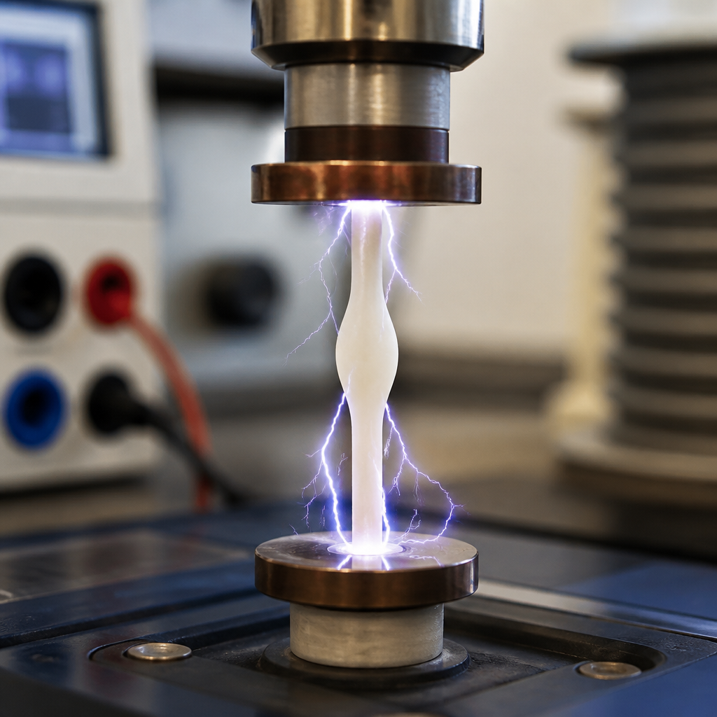
Engineers commonly evaluate electrical stability through standardized tests. ASTM D149 measures dielectric breakdown voltage of solid electrical insulating materials. ASTM D257 covers DC resistance or conductance, including volume resistivity and surface resistivity. ASTM D150 addresses AC loss characteristics and permittivity. IEC 60112 measures comparative tracking index, important for contamination resistance on surfaces. UL 746 and related insulation system approaches connect material behavior to end-use safety. These methods matter, but none should be read in isolation. A high initial dielectric strength does not guarantee resistance to long-term partial discharge, and a favorable room-temperature resistivity can collapse in warm, wet conditions. Good engineering starts by asking not only what property is high, but under what field, frequency, environment, and aging history it remains high.
Core electrical properties that define long-term performance
The main electrical properties for polymer selection are dielectric strength, dielectric constant, dissipation factor, volume resistivity, surface resistivity, arc resistance, tracking resistance, and partial discharge endurance. Dielectric strength is often quoted in kilovolts per millimeter, but it is strongly thickness dependent and sensitive to electrode geometry, defects, and test ramp rate. Dielectric constant, also called relative permittivity, describes how much electric energy the material stores; low values are preferred in high-frequency electronics to reduce signal delay and capacitive coupling. Dissipation factor, often expressed as tan delta, captures how much energy becomes heat during AC operation. High tan delta can lead to thermal runaway in severe electric fields.
Volume resistivity indicates how strongly the bulk material resists current flow, while surface resistivity reflects leakage across the surface, where humidity, dust, and residues often dominate. Tracking resistance becomes critical in appliances, automotive connectors, and switchgear because leakage can carbonize the surface and create a conductive path. Partial discharge endurance matters in medium- and high-voltage insulation, where tiny voids or interfaces can ionize repeatedly and erode the polymer over time. In real projects, I prioritize the interaction among these properties. For example, epoxy systems for electronics may offer excellent adhesion and mechanical strength, but if cure quality leaves microvoids, partial discharge resistance may be compromised. Likewise, carbon-filled antistatic compounds can meet a target resistivity range while sacrificing dielectric breakdown strength, making them unsuitable near high electric fields.
How polymer chemistry and structure control stability
Polymer chemistry governs charge transport, dipolar polarization, moisture affinity, and thermal endurance. Nonpolar polymers such as polyethylene and polypropylene usually exhibit low dielectric loss and high resistivity because their molecular chains contain few polar groups. That is one reason cross-linked polyethylene became a major insulation material for power cables. By contrast, polar polymers such as polyamide, polycarbonate, and many thermosets can show higher permittivity and greater environmental sensitivity because permanent dipoles respond to electric fields and water absorption changes mobility. Fluoropolymers, including PTFE, FEP, and PFA, are widely valued for excellent dielectric behavior, chemical resistance, and high-temperature stability, though cost and processing complexity are tradeoffs.
Morphology also matters. Higher crystallinity often reduces charge mobility in amorphous regions and can improve barrier performance, but crystalline-amorphous interfaces may become sites for field enhancement if morphology is poorly controlled. Crosslinking can improve thermal shape retention and slow viscous flow under heat, yet excessive crosslink density may increase brittleness or trap residual stresses. Fillers introduce another layer. Glass fiber raises stiffness but can create anisotropy and interfacial defects. Mineral fillers may improve tracking resistance in some systems. Conductive fillers such as carbon black, carbon nanotubes, or graphene are useful for electrostatic discharge control, but they must be dispersed carefully because localized agglomerates can create hot spots and unstable conduction networks. Processing history, including melt temperature, residence time, drying, contamination control, and cure schedule, frequently explains why nominally identical polymers perform differently in electrical aging tests.
Environmental and service conditions that cause electrical drift
Most polymer electrical failures are not caused by voltage alone. They result from the combined action of electric field, temperature, humidity, contaminants, oxygen, ultraviolet exposure, and mechanical stress. Moisture is especially influential because water increases surface leakage and, in hygroscopic polymers, modifies bulk dielectric behavior. Nylon is a classic example: as it absorbs moisture, resistivity drops and dielectric strength can decline. Temperature accelerates charge transport, oxidation, additive migration, and mechanical relaxation. In wire insulation, repeated thermal cycling can open interfacial gaps that intensify partial discharge activity. Surface contamination, including flux residues, salts, oils, or dust, lowers tracking resistance dramatically, which is why clean processing and enclosure design matter as much as resin choice.
Frequency is another overlooked factor. A polymer that performs well under DC may show unacceptable dielectric heating at higher AC frequencies because dipoles cannot reorient without energy loss. This is relevant in power electronics, RF substrates, and electric vehicle inverters using fast-switching wide-bandgap semiconductors. Radiation can embrittle or crosslink polymers depending on chemistry, changing both mechanical and electrical properties. Mechanical stress matters because cracks, crazes, and voids distort the local electric field. In my experience with molded insulating parts, knit lines and sink-related porosity often become the hidden origins of dielectric failure, even when the bulk resin is sound. Stable electrical performance therefore requires a service-life view, not just a virgin-material view.
Comparing common polymers used for electrical insulation
No polymer is best for every electrical application. Selection depends on voltage class, frequency, temperature, environment, flammability requirements, manufacturability, and cost. The table below summarizes broad tendencies engineers use during early screening before detailed qualification testing.
| Polymer | Typical electrical strengths | Main limitations | Common applications |
|---|---|---|---|
| PE / XLPE | High resistivity, low dielectric loss, good cable insulation performance | Thermal limits lower than some engineering polymers; treeing must be managed in HV service | Power cables, wire insulation |
| PP | Low dielectric constant and loss, good chemical resistance | Can become brittle at low temperature without modification | Film capacitors, housings |
| PVC | Good insulation with flexible formulations, economical | Plasticizer migration and thermal stability concerns; dielectric properties depend strongly on formulation | Cable jackets, appliance wiring |
| PA | Good mechanical strength and processability | Moisture absorption reduces resistivity and dimensional stability | Connectors, coil formers |
| PC | Useful dielectric performance with toughness and transparency | Stress cracking and tracking performance must be checked by grade | Electronic housings, lighting components |
| Epoxy | Excellent adhesion, encapsulation, and tailored dielectric properties | Voids, cure shrinkage, and thermal mismatch can limit long-term endurance | PCB laminates, potting, insulators |
| PTFE | Outstanding dielectric stability over temperature and frequency | High cost and more specialized processing | RF cables, aerospace wiring, high-end seals |
These are starting points, not final decisions. Grade-to-grade differences, flame-retardant packages, reinforcement levels, and processing routes can shift performance enough to change the correct choice.
Failure mechanisms engineers need to anticipate
The most important electrical failure mechanisms in polymers are dielectric breakdown, thermal breakdown, electrical treeing, tracking, arc erosion, space-charge accumulation, and aging induced by oxidation or hydrolysis. Dielectric breakdown occurs when the local electric field exceeds the material’s ability to resist charge acceleration, causing a sudden conductive path. Thermal breakdown is more gradual: dielectric losses generate heat, heat lowers resistance, and the resulting positive feedback accelerates failure. Electrical treeing is common in high-voltage insulation containing defects or contaminants. Branch-like damage grows through the polymer under repetitive stress until complete breakdown occurs.
Tracking is a surface phenomenon promoted by moisture and contamination; once carbonized paths form, failure can progress rapidly. Arc erosion is especially relevant in switching devices and relay components where repeated arcs attack the surface. Space charge deserves attention in DC and high-field applications because trapped charge distorts the local electric field and can shorten life even when average stress looks acceptable. Material aging compounds all of these effects. Oxidation can embrittle polyolefins, hydrolysis can attack susceptible condensation polymers, and additive depletion can remove stabilization that the original datasheet quietly relied upon. The lesson is straightforward: if the design includes high field gradients, contamination risk, or long lifetimes, engineers should test the likely failure mode directly rather than assuming a generic insulation rating covers it.
Testing, qualification, and design practices that improve stability
Reliable selection starts with matching tests to the application physics. For connector bodies in humid environments, compare comparative tracking index, insulation resistance after conditioning, and dimensional stability after moisture exposure. For potting compounds around high-voltage electronics, examine dielectric strength, partial discharge inception voltage, thermal conductivity, coefficient of thermal expansion, and void content after cure. For cable insulation, water tree resistance, elongation retention after aging, and long-term thermal endurance become central. Accelerated aging is useful, but it must reflect real stress combinations. Elevated temperature alone will not predict contamination-induced tracking, and a short dielectric breakdown test will not reveal slow electrochemical degradation.
Design discipline improves outcomes as much as material choice. Smooth electric field geometry, generous creepage and clearance distances, controlled wall thickness, and good venting to minimize voids are fundamental. Dry hygroscopic resins before molding, monitor melt residence time, and control regrind levels because degraded polymer chains often show lower resistivity and poorer breakdown behavior. In assembly, keep ionic residues low; many field problems blamed on resin quality are actually cleanliness problems. When using filled conductive compounds for static control, measure stability after abrasion and humidity cycling, not only at shipment. Finally, build a qualification matrix that includes baseline properties, environmental conditioning, and retesting after aging. That approach turns electrical stability from a datasheet assumption into a verified design attribute.
Exploring the electrical stability of polymer materials reveals a simple truth: electrical performance is inseparable from chemistry, structure, environment, and processing. A polymer is not electrically stable because one catalog value looks impressive; it is stable when resistivity, dielectric loss, breakdown resistance, and surface behavior remain within design limits throughout real service conditions. For the broader electrical properties topic, this hub provides the framework that connects insulation resistance, dielectric constant, dissipation factor, tracking resistance, and breakdown behavior into one decision process. The practical benefit is better material selection and fewer surprises during qualification or field use.
The strongest choices come from linking application stresses to known material tendencies. Polyolefins often excel in low-loss insulation, fluoropolymers deliver exceptional dielectric consistency, epoxies enable robust encapsulation when voids are controlled, and hygroscopic polymers demand careful moisture management. Standards such as ASTM D149, ASTM D257, ASTM D150, and IEC 60112 give useful measurements, but lasting confidence comes from combining those tests with aging studies that reflect temperature, humidity, contamination, frequency, and mechanical stress. When engineers do that, they stop treating electrical stability as an abstract material claim and start using it as a design tool.
Use this article as the starting point for every deeper page under electrical properties, from dielectric strength and resistivity to tracking and partial discharge. Build your next material comparison around service conditions, failure mechanisms, and validated test data, and your polymer choices will be safer, longer lasting, and easier to defend.
Frequently Asked Questions
What does electrical stability mean in polymer materials?
Electrical stability describes how consistently a polymer maintains its intended electrical behavior over time and under changing real-world conditions. In other words, it is not just about whether a material insulates well on day one, but whether it continues to insulate, dissipate static, or conduct within a controlled range after exposure to voltage, heat, humidity, mechanical loading, contamination, and aging. This makes electrical stability a broader and more practical concept than any single laboratory measurement.
For example, a polymer may show excellent dielectric strength in a short test, yet gradually lose performance in service because moisture increases ionic conduction, thermal cycling creates microcracks, or electrical stress accelerates chemical degradation. Another material may begin with moderate resistivity but remain highly predictable for years, which can be more valuable in applications where long-term reliability matters more than peak initial performance. Engineers therefore evaluate electrical stability as a combination of resistance to breakdown, retention of dielectric properties, control of leakage current, and predictable behavior across the full service environment.
This is especially important in components such as cable insulation, connector housings, battery separators, encapsulants, and electronic packaging. In all of these applications, failure is often not caused by one dramatic event, but by slow property drift. A stable polymer helps prevent unexpected tracking, arcing, charge buildup, dielectric loss changes, and insulation failure, all of which can affect safety, product life, and regulatory compliance.
Why isn’t a single property like dielectric strength enough to judge long-term electrical performance?
Dielectric strength is useful, but it only captures one aspect of performance: the voltage at which a material fails under a specific set of test conditions. Real applications are far more complex. A polymer component may operate for years at voltages well below its initial dielectric strength and still experience gradual electrical deterioration due to heat, moisture, repeated stress, chemical exposure, or partial discharge activity. That means a strong short-term test result does not automatically translate into long-term electrical reliability.
Electrical behavior in polymers is highly dependent on time and environment. Volume resistivity may drop as humidity rises. Dielectric constant and dissipation factor may shift with temperature and frequency. Mechanical strain can create defects or alter the internal structure, changing how electric fields are distributed. Additives, fillers, plasticizers, and flame retardants can also influence conductivity pathways, water uptake, and aging behavior. As a result, two materials with similar dielectric strength can perform very differently once installed in a demanding application.
Engineers typically need a portfolio of data rather than a single number. They look at dielectric strength, insulation resistance, volume and surface resistivity, dielectric constant, dielectric loss, comparative tracking resistance, arc resistance, aging performance, and environmental durability. More importantly, they evaluate how those values change over time. The most suitable polymer is often the one that remains predictable after prolonged service, not the one with the highest headline number in an idealized test.
Which factors most strongly affect the electrical stability of polymers in service?
The most influential factors are voltage, temperature, humidity, time, and mechanical stress, but their importance lies in how they interact rather than how they act independently. Electrical stress can promote charge injection, localized heating, partial discharge, and eventual breakdown. Elevated temperature accelerates molecular motion, oxidation, additive migration, and thermal aging, all of which can alter resistivity and dielectric performance. Humidity can be especially damaging in susceptible polymers because absorbed water may increase ionic conduction, lower insulation resistance, and encourage surface tracking under contamination.
Time is critical because many degradation processes are cumulative. A polymer that performs acceptably in a short test may slowly embrittle, crack, oxidize, or absorb contaminants after months or years of use. Mechanical stress adds another layer of complexity by generating microvoids, crazing, interfacial defects, or dimensional changes that distort the electric field. In filled or reinforced systems, differences between the polymer matrix and the filler can create local weak points where degradation begins. Repeated vibration, flexing, or compression can therefore reduce electrical stability even when the material’s base chemistry looks suitable on paper.
Surface condition and formulation details matter as well. Processing history, residual moisture, contamination, filler dispersion, and void content can all influence electrical stability. Even the geometry of the part plays a role, because sharp corners and thin sections can intensify electric fields. For this reason, engineers usually assess the complete system: the polymer chemistry, additive package, manufacturing method, expected environment, and operating duty cycle. Electrical stability is ultimately a performance outcome shaped by both material selection and application design.
How do engineers test the electrical stability of polymer materials?
Testing typically combines baseline electrical measurements with accelerated aging and environmental exposure studies. Baseline tests may include dielectric strength, volume resistivity, surface resistivity, insulation resistance, dielectric constant, and dissipation factor. These provide an initial picture of how the polymer behaves electrically. However, because stability is about retention and predictability, the material is then exposed to conditions that simulate or accelerate real service, such as elevated temperature, humidity cycling, continuous voltage stress, thermal shock, salt fog, chemical exposure, and mechanical fatigue.
After aging, engineers remeasure the key electrical properties and compare them to the original values. They also look for failure modes such as tracking, erosion, cracking, embrittlement, discoloration, partial discharge damage, and loss of dimensional integrity. In some applications, long-duration testing under electrical bias is essential because it can reveal gradual changes that short tests miss. For outdoor, automotive, battery, and power applications, test programs may also include contamination resistance, arc resistance, comparative tracking index, and resistance to electrochemical degradation at interfaces.
The best test strategy is application-specific. A connector housing, for instance, may need strong resistance to tracking and moisture-related leakage on exposed surfaces. A battery separator may require stable ionic and electrical behavior under heat, electrolyte exposure, and compression. A cable jacket may need to preserve insulation performance despite flexing and weathering. Good engineering practice is to match the test methods to the real failure mechanisms the part is likely to encounter, then use the results to compare not only initial performance but also stability margins over expected service life.
How can manufacturers improve the electrical stability of polymer components?
Improving electrical stability starts with material selection, but it does not end there. Manufacturers need to choose a polymer whose base chemistry is inherently suited to the electrical and environmental demands of the application. Some polymers resist moisture uptake better than others. Some retain dielectric properties more effectively at elevated temperatures. Some are more resistant to tracking, hydrolysis, oxidation, or partial discharge damage. Once the base resin is selected, the additive package must be carefully engineered because stabilizers, fillers, flame retardants, pigments, and plasticizers can either improve or compromise long-term electrical behavior.
Processing control is equally important. Excess moisture, poor filler dispersion, contamination, internal voids, weld lines, and thermal degradation during molding or extrusion can all reduce electrical stability. A well-designed process minimizes defects that concentrate electric fields or create unintended conductive pathways. Part design also matters. Smooth geometries, adequate wall thickness, controlled tolerances, and avoidance of sharp edges help reduce localized electrical stress. In assemblies, proper sealing, creepage distance, clearance, and interface design can further protect the polymer from moisture intrusion and surface leakage.
Finally, manufacturers improve stability by validating the material in realistic service conditions rather than relying only on datasheet values. Long-term aging studies, biased humidity testing, thermal cycling, and field-relevant qualification protocols help identify whether the polymer will remain predictable over time. In practice, the most successful approach is a systems approach: combine the right polymer chemistry, the right formulation, disciplined manufacturing, and application-specific testing. That is how a component moves from looking good in the lab to performing reliably for years in the field.