Simulation software has become a core capability in polymer engineering because modern products must be lighter, cheaper, faster to manufacture, and more reliable under increasingly demanding service conditions. In practice, polymer engineering covers the design, processing, testing, and lifecycle management of plastics, elastomers, thermosets, composites, films, foams, and additive manufacturing feedstocks. Simulation software refers to digital tools that predict how these materials will flow, cure, crystallize, deform, fail, age, and interact with tooling before engineers cut steel or run production trials. For teams working in product development, processing, quality, and research, these tools reduce uncertainty and make decisions visible early.
The importance of simulation in polymer engineering comes from the material behavior itself. Metals are difficult enough, but polymers introduce viscoelasticity, nonlinear stress-strain response, strong temperature dependence, molecular orientation, pressure-sensitive shrinkage, moisture effects, and process histories that materially change performance. I have seen two injection molded parts built from the same nominal resin perform very differently because gate position, cooling imbalance, and fiber orientation created different internal structures. Without simulation, those differences are often discovered after tooling investment, customer complaints, or failed validation tests. With simulation, they can be anticipated, quantified, and designed around.
This article serves as a hub for software and tools used across polymer engineering. It explains what each class of simulation does, where it fits in the development process, what inputs matter, and how engineers connect predictions to lab data and factory reality. It also clarifies an important point: simulation does not replace testing or engineering judgment. It improves both by narrowing the design space, exposing hidden tradeoffs, and making process-structure-property relationships easier to manage. For educational teams, design engineers, and manufacturing leaders, understanding simulation software is now essential to building efficient workflows and better polymer products.
Why simulation matters across the polymer product lifecycle
Simulation software matters because polymer failures are rarely caused by a single variable. A brittle snap fit may trace back to weld line weakness, over-dried resin, excessive regrind, aggressive assembly loads, or chemical exposure in the field. A warped housing may result from unbalanced filling, uneven mold temperature, post-mold crystallization, or rib geometry that locks in stress. In day-to-day engineering work, the value of simulation is that it lets teams test these interacting variables in a controlled digital environment. Engineers can compare concepts quickly, identify high-risk features, and prioritize physical experiments where they will produce the most learning.
Across the lifecycle, different tools answer different questions. During concept design, structural solvers estimate stiffness, impact response, creep, and fatigue. During tool design, mold filling software predicts pressure, temperature, air traps, weld lines, sink marks, and shrinkage. During material selection, databases and constitutive models help compare unfilled polymers, fiber-reinforced grades, elastomers, and blends. During validation, thermal and chemical simulations estimate heat aging, diffusion, solvent exposure, and dimensional change. During production, digital process tools support troubleshooting, cycle time reduction, and root-cause analysis. The common outcome is fewer surprises between CAD release and field performance.
Core categories of polymer engineering simulation software
Polymer engineering uses several major software categories, each tied to a distinct physical problem. Computer-aided engineering platforms handle linear and nonlinear structural analysis, thermal analysis, vibration, contact, and buckling. Mold filling and process simulation tools model injection molding, extrusion, blow molding, thermoforming, compression molding, resin transfer molding, and curing. Computational fluid dynamics tools address mixing, die flow, and cooling fluid behavior where standard process packages are not enough. Materials informatics and databases organize rheology, PVT behavior, creep curves, fatigue data, thermal conductivity, and chemical resistance information needed for accurate models.
Examples widely used in industry include Autodesk Moldflow and Moldex3D for injection molding analysis, Ansys and Abaqus for structural and multiphysics simulation, COMSOL Multiphysics for custom coupled models, Digimat for micromechanics and material modeling, Altair Inspire and HyperWorks tools for design studies, and specialized packages for extrusion die design or composite layup simulation. No single platform covers everything equally well. Experienced teams typically use a stack: CAD for geometry, a process tool for manufacturing physics, a finite element tool for service loads, and data systems for validated material properties. Choosing the stack depends on product complexity, team skill, and the decisions the software must support.
| Software category | Primary questions answered | Typical outputs | Common example tools |
|---|---|---|---|
| Structural and thermal CAE | Will the part survive loads, heat, creep, and impact? | Stress, strain, deflection, life, temperature fields | Ansys, Abaqus, Altair |
| Molding and process simulation | Can the part be manufactured consistently and without defects? | Fill time, pressure, weld lines, sink, warpage, cooling time | Moldflow, Moldex3D |
| CFD and mixing analysis | How do polymer melts and cooling fluids move through channels and dies? | Velocity, shear rate, residence time, temperature distribution | Ansys Fluent, COMSOL |
| Material modeling tools | How should complex polymer behavior be represented mathematically? | Constitutive models, homogenized properties, orientation effects | Digimat, MCalibration |
How simulation supports material selection and characterization
Good polymer simulation starts with good material data. This is where many projects struggle. A generic modulus value from a datasheet is not enough when predicting a part that sees heat, long-term load, humidity, or multiaxial stress. Engineers need temperature-dependent elastic properties, viscoelastic curves, coefficient of thermal expansion, specific heat, thermal conductivity, PVT data, viscosity as a function of shear rate and temperature, and often creep, fatigue, and fracture data. For semicrystalline polymers such as polypropylene, POM, PA, and PEEK, crystallinity and cooling rate can strongly alter stiffness, shrinkage, and chemical resistance. For filled compounds, orientation matters as much as the nominal filler percentage.
In practical workflows, characterization data comes from supplier files, standardized testing, and internal calibration. Common standards include ASTM and ISO methods for tensile behavior, DSC for melting and crystallization, DMA for storage modulus and damping, TGA for thermal stability, capillary or rotational rheometry for viscosity, and dilatometry or PVT testing for shrinkage behavior. When I have built simulation models for molded parts, the biggest improvements often came not from meshing tricks but from replacing generic material cards with calibrated data measured near the real process window. That step turns simulation from a presentation tool into a decision tool.
Injection molding simulation and defect prevention
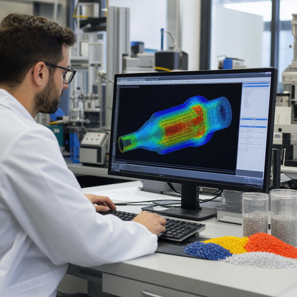
Injection molding is the area where polymer simulation software has had the most visible impact because tooling is expensive and process defects are strongly linked to geometry and thermal history. A mold filling analysis predicts how the melt front advances through the cavity, how much pressure is required, where the flow hesitates, where weld lines form, whether air becomes trapped, and how long the part takes to freeze. Pack and cool analysis then estimates volumetric shrinkage, differential cooling, residual stress, sink tendency, and warpage. For fiber-filled polymers, advanced solvers also estimate orientation tensors that influence anisotropic mechanical performance.
These predictions directly support design and manufacturing choices. Gate location can be moved to reduce weld lines near clips or bosses. Wall thickness can be adjusted to reduce pressure drop or sink. Cooling circuits can be redesigned to improve mold temperature balance. Packing pressure profiles can be tuned to cut dimensional variation. In one common real-world scenario, a consumer electronics housing shows corner lift after ejection. Simulation often reveals that one side of the mold runs hotter, leading to uneven shrinkage. Correcting the cooling layout or process settings before steel changes saves weeks and prevents expensive tool rework.
Structural analysis for durability, creep, and long-term performance
Polymers are often selected because they reduce weight and integrate functions, but they must still survive assembly loads, impacts, vibration, and years of service. Structural simulation helps engineers check whether a part is stiff enough, whether local stresses exceed allowable values, and where geometry should change. However, unlike many metal parts, polymer components often fail by creep, stress relaxation, notch sensitivity, or temperature-induced softening rather than simple yield under a single load case. That means the solver setup must reflect time, temperature, and contact conditions realistically. Using room-temperature short-term tensile data for a hot under-hood bracket is a classic modeling mistake.
Well-built structural simulations are especially valuable for snap fits, pressure vessels, enclosures, gears, seals, and living hinges. For snap fits, nonlinear contact and strain localization determine whether repeated assembly causes whitening or fracture. For gears, tooth deflection, frictional heating, and moisture absorption can shift backlash and wear behavior. For pressure-bearing parts made from reinforced nylon or PPS, creep under sustained stress may control design more than burst strength. Engineers commonly combine finite element analysis with physical coupon and component testing to calibrate allowable strains. That hybrid approach is the most reliable route to durable polymer design.
Extrusion, blow molding, thermoforming, and composites
Polymer engineering extends far beyond injection molding, and simulation software now covers many continuous and semi-continuous processes. In extrusion, engineers use die flow analysis to predict pressure drop, shear heating, residence time, melt uniformity, and die swell. These outputs help balance multi-outlet dies, reduce gauge variation in sheet and film, and prevent degradation in heat-sensitive materials such as PVC. In blow molding, software predicts parison sag, thickness distribution, and final wall variation so designers can improve bottle performance without adding unnecessary material. In thermoforming, heating balance and sheet thinning predictions are essential for trays, appliance liners, and medical packaging.
For thermosets and composites, simulation becomes even more process-sensitive. Cure kinetics, exotherm, viscosity evolution, and fiber architecture all influence defects and final properties. Compression molding of sheet molding compound, resin transfer molding of structural composites, and additive manufacturing of reinforced pellets all benefit from digital process models. Aerospace and wind energy sectors rely on these tools to control void content, spring-in, cure distortion, and laminate performance. The same principles increasingly apply in automotive battery enclosures and sporting goods. As composite use expands, software that links process history to structural behavior is becoming a standard requirement rather than a specialist option.
Building an effective software workflow and team capability
The best simulation software does not deliver value by itself; the workflow around it does. Effective teams define the decision first, then choose the tool, model detail, and validation plan needed to answer that decision. A quick gate study for an injection molded bracket may only require comparative results, while a medical device housing facing regulatory scrutiny may require rigorous traceability of geometry revisions, material cards, assumptions, and verification tests. Version control, CAD cleanup practices, mesh quality standards, and documented boundary conditions are basic disciplines that separate trustworthy simulation programs from visually impressive but unreliable reports.
Skill development matters just as much as licenses. Engineers need literacy in rheology, heat transfer, nonlinear mechanics, and polymer processing to interpret results correctly. They also need enough factory exposure to recognize when assumptions are unrealistic. I have seen excellent analysts improve dramatically after spending time with toolmakers, molders, and test labs because they learned where data noise and process variation really come from. For organizations building this capability, the most practical path is to start with recurring failure modes, validate against a small number of high-value products, create internal modeling standards, and expand from there. Use this hub as a starting point, then connect each software category to deeper process, materials, and testing resources across your educational library.
Simulation software has changed polymer engineering from a largely trial-and-error discipline into a more predictive, data-driven practice. Its real role is not to eliminate prototypes or guarantee perfect outcomes. Its role is to sharpen questions, reveal hidden interactions, and help teams spend their time and money on the right experiments, tooling choices, and design revisions. When software is paired with calibrated material data, sound physics, and plant-level experience, it reduces scrap, shortens development cycles, improves dimensional stability, and raises confidence in long-term performance.
For a hub page on software and tools, the key takeaway is clear: polymer engineers need a connected view of process simulation, structural analysis, material characterization, and validation workflows. Injection molding analysis, extrusion modeling, thermal studies, creep prediction, and composite cure simulation are not isolated specialties; they are linked parts of the same process-structure-property chain. Teams that understand those links make better decisions earlier, whether they are designing a consumer housing, a medical component, an under-hood connector, or a structural composite panel.
If you are building knowledge under educational resources, use this article as the entry point for the full software and tools topic. Map your next reading to your biggest need: material data quality, mold filling, durability analysis, extrusion control, or composite process modeling. Then compare software outputs against real test results and production behavior. That disciplined loop is where simulation delivers its greatest value in polymer engineering.
Frequently Asked Questions
1. What is simulation software in polymer engineering, and why is it so important today?
Simulation software in polymer engineering is a class of digital tools used to predict how polymer materials and polymer-based products will behave during design, processing, testing, and real-world use. Depending on the application, these tools can model melt flow in injection molding, curing in thermosets, fiber orientation in composites, heat transfer in extrusion, warpage in molded parts, stress and strain in service, permeability in films, foaming behavior, and even the layer-by-layer behavior of additive manufacturing feedstocks. In simple terms, simulation allows engineers to test ideas virtually before committing to tooling, production changes, or physical prototypes.
Its importance has grown because product requirements have become much more demanding. Manufacturers are expected to make components that are lighter, lower cost, faster to produce, and more reliable, while also meeting tighter performance, quality, and sustainability targets. Polymers are also being used in more critical applications, including automotive, medical, electronics, packaging, aerospace, and industrial systems. In these environments, small design or processing errors can lead to dimensional instability, sink marks, residual stress, part failure, excessive scrap, or shortened product life. Simulation helps reveal those risks early, when changes are still practical and affordable.
Another major reason simulation matters is the complexity of polymer behavior itself. Unlike many simple engineering materials, polymers are highly sensitive to temperature, shear rate, cooling history, moisture, filler content, crystallization, and processing conditions. A part that looks acceptable in CAD may behave very differently once it is molded, extruded, thermoformed, foamed, or printed. Simulation software gives engineers a more realistic view of that behavior, which improves decisions across material selection, tool design, process setup, and performance validation. For many polymer organizations, simulation is no longer a nice-to-have capability; it is a core part of modern engineering and manufacturing strategy.
2. How does simulation software help improve polymer product design and material selection?
Simulation software improves polymer product design by helping engineers understand whether a concept will perform as intended before physical samples are made. In the early design phase, software can identify areas where a part may be too thin to fill properly, too thick and prone to sink or long cycle times, or too weak under expected loading conditions. It can also show where stress concentrations may develop, where weld lines may reduce strength or appearance, and where cooling differences may cause distortion. This allows teams to refine geometry early rather than discovering problems after tooling has already been built.
Material selection is another area where simulation delivers major value. Polymer engineers often must choose among multiple families of materials, such as commodity plastics, engineering resins, thermosets, elastomers, reinforced compounds, films, foams, or printable feedstocks. Each option brings a different combination of stiffness, toughness, impact resistance, heat resistance, shrinkage behavior, chemical resistance, and processability. Simulation helps compare those materials in the context of an actual part and process, rather than relying only on generic datasheet values. For example, one resin may appear suitable on paper but may produce excessive warpage in a thin-wall geometry, while another may fill more consistently and maintain dimensional stability after cooling.
Simulation is especially useful when lightweighting is a key objective. Engineers can test rib placement, wall thickness reduction, fiber reinforcement strategies, or alternative polymer grades to reduce mass without sacrificing structural performance. In composites, simulation can help predict fiber orientation and anisotropic behavior, which is essential for making realistic strength assessments. In films and packaging, it can be used to balance barrier performance, flexibility, and processing efficiency. In additive manufacturing, it can support feedstock choice and print strategy to reduce defects and improve final properties. The result is a more informed, data-driven design process that shortens development time and improves confidence in material decisions.
3. What kinds of polymer processing problems can simulation software predict and reduce?
Simulation software is widely used to predict processing-related issues before they appear on the production floor. In injection molding, for example, it can identify short shots, air traps, weld lines, sink marks, hesitation effects, uneven filling, excessive clamp force requirements, and cooling imbalances. It can also estimate shrinkage and warpage, which are among the most important concerns for dimensional accuracy and assembly fit. By evaluating gate location, runner design, mold temperature, injection speed, packing profile, and cooling channel layout, engineers can reduce trial-and-error during tool launch and move toward a more stable process more quickly.
In extrusion and film processing, simulation can be used to study die flow balance, melt temperature distribution, pressure drop, residence time, layer uniformity, and drawdown behavior. These predictions help reduce gauge variation, flow instabilities, and other defects that affect product quality and throughput. For thermoforming, simulation can support sheet heating strategy, thickness distribution, and final part shape. For foams, it can help engineers understand cell growth behavior, density distribution, and thermal effects. In composites processing, simulation may be used to model resin infusion, curing, fiber placement, compaction, and void formation. In additive manufacturing, it can predict bead shape, thermal history, residual stress, and distortion across printed layers.
One of the biggest advantages of simulation is that it links processing conditions to final part quality. Instead of treating defects as isolated shop-floor issues, engineers can see the underlying mechanisms that cause them. That means they can correct root causes rather than just reacting to symptoms. This is especially valuable in polymer manufacturing because processing has such a strong influence on final properties. A part made from the right material can still fail if the flow path, cooling, orientation, or cure profile is poorly controlled. Simulation helps reduce scrap, shorten setup time, improve repeatability, and support more robust manufacturing windows across a wide range of polymer processes.
4. Can simulation software improve product reliability and lifecycle performance for polymer components?
Yes, and this is one of the most strategic uses of simulation in polymer engineering. Polymer components are often exposed to mechanical loads, heat, humidity, chemicals, UV radiation, cyclic stress, creep conditions, and long service lives. Simulation software helps engineers evaluate how a component may respond under these conditions, both immediately and over time. Structural analysis can estimate deflection, stress distribution, fatigue-prone regions, and failure risks. Thermal analysis can show how elevated temperatures affect shape retention or mechanical performance. Specialized polymer models can also account for viscoelasticity, creep, relaxation, and time-dependent deformation, which are critical because polymers do not behave like purely elastic materials.
Lifecycle performance is particularly important in applications where safety, durability, or warranty costs are major concerns. In automotive systems, for instance, polymer parts may need to withstand vibration, under-hood heat, fluids, and repeated loading. In medical products, consistency and biocompatible material behavior may be essential. In electronics, thermal cycling and dimensional precision can determine long-term reliability. In packaging, drop resistance, seal integrity, and barrier retention may be the main concerns. Simulation helps engineers test these conditions virtually so they can strengthen vulnerable areas, choose more suitable materials, or adjust processing conditions that influence long-term behavior.
Another key benefit is the ability to connect manufacturing history with in-service performance. A polymer part’s reliability is often affected by processing-induced residual stresses, fiber orientation, crystallinity, void content, or cure state. Advanced simulation workflows can carry information from process simulation into structural or durability analysis, creating a more realistic digital representation of the finished part. That leads to better failure prediction and better engineering decisions. While physical testing remains essential for final validation, simulation makes those tests more targeted and efficient by narrowing down the highest-risk scenarios before expensive qualification work begins.
5. What are the main business and engineering benefits of using simulation software in polymer development?
The most immediate business benefit is reduced development cost. Simulation lowers the number of physical prototypes, tooling changes, and production trials required to reach an acceptable design and process. In polymer engineering, those savings can be substantial because tooling for molded, extruded, or composite parts can be expensive, and process troubleshooting can consume significant time and material. By identifying likely problems early, simulation helps prevent late-stage redesigns, reduces startup scrap, and shortens the path from concept to production.
There are also major engineering benefits. Teams gain better visibility into how materials, geometry, and processing interact, which leads to better decisions and a more consistent design methodology. Simulation supports cross-functional collaboration because designers, materials engineers, tooling specialists, process engineers, and quality teams can work from the same predictive information. Instead of relying mainly on experience or trial-and-error, they can compare alternatives quantitatively and justify decisions with data. This is especially valuable when dealing with advanced materials such as reinforced polymers, thermosets, multilayer films, foams, and additive manufacturing feedstocks, where behavior can be difficult to predict intuitively.
Longer term, simulation contributes to competitiveness and innovation. Companies can bring new polymer products to market faster, evaluate more design options within the same schedule, and improve product quality while controlling manufacturing risk. It also supports sustainability goals by reducing waste, avoiding unnecessary prototypes, optimizing material usage, and improving energy efficiency through better process design. Perhaps most importantly, simulation helps organizations build a more predictive engineering culture. Rather than waiting for failures to reveal weaknesses, teams can anticipate them, design around them, and make polymer development more efficient, reliable, and